All projects

FEA: stress concentration and symmetry

A series of Ansys Workbench studies from my component design course: refining a mesh, finding stress concentrations around holes, and testing how half and quarter symmetry models compare to a full model.

Software
Ansys Workbench (Mechanical), SolidWorks
Material
Structural steel, E = 200 GPa
Course
Component design
Timeline
Fall 2026
Models
250 × 50 × 10 mm beam, tensile dogbone
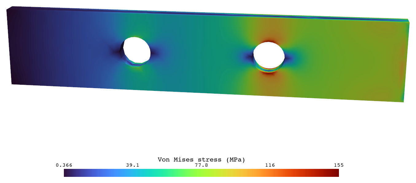
Stress contour plot of a beam with two holes, red at the hole edges
Von Mises stress in the steel beam with two 20 mm holes. Stress peaks at the hole edges.

Beam with holes

I modeled a 250 × 50 × 10 mm steel beam with two 20 mm holes and meshed it at several densities, from a coarse 84 elements up to 25,654 elements (39,871 nodes). In every run the stress concentrates at the top and bottom edges of the holes.
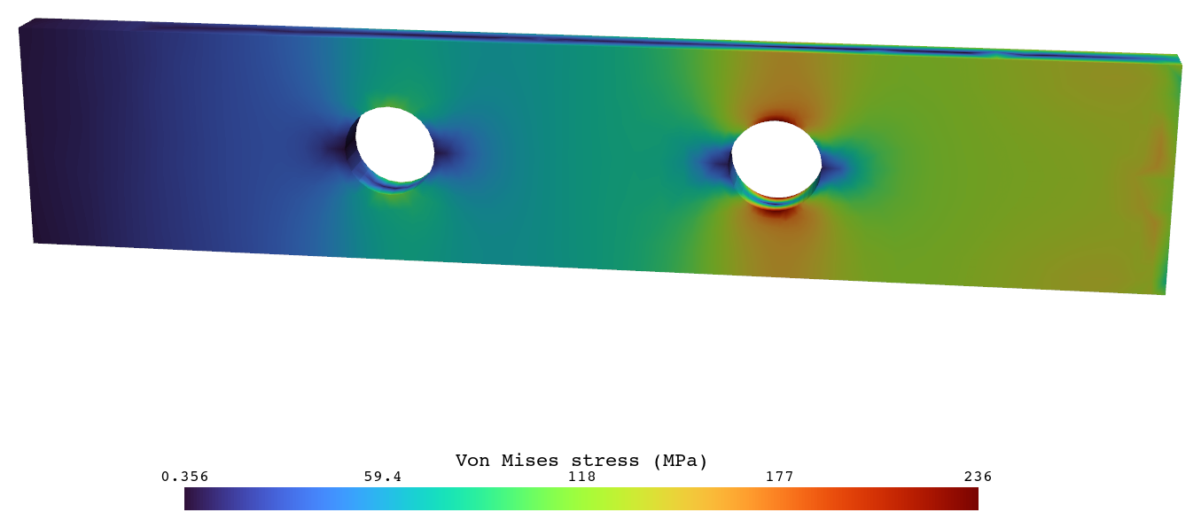
Stress contour plot of the beam with two holes on the refined mesh
Refined mesh: 25,654 elements.

Symmetry models

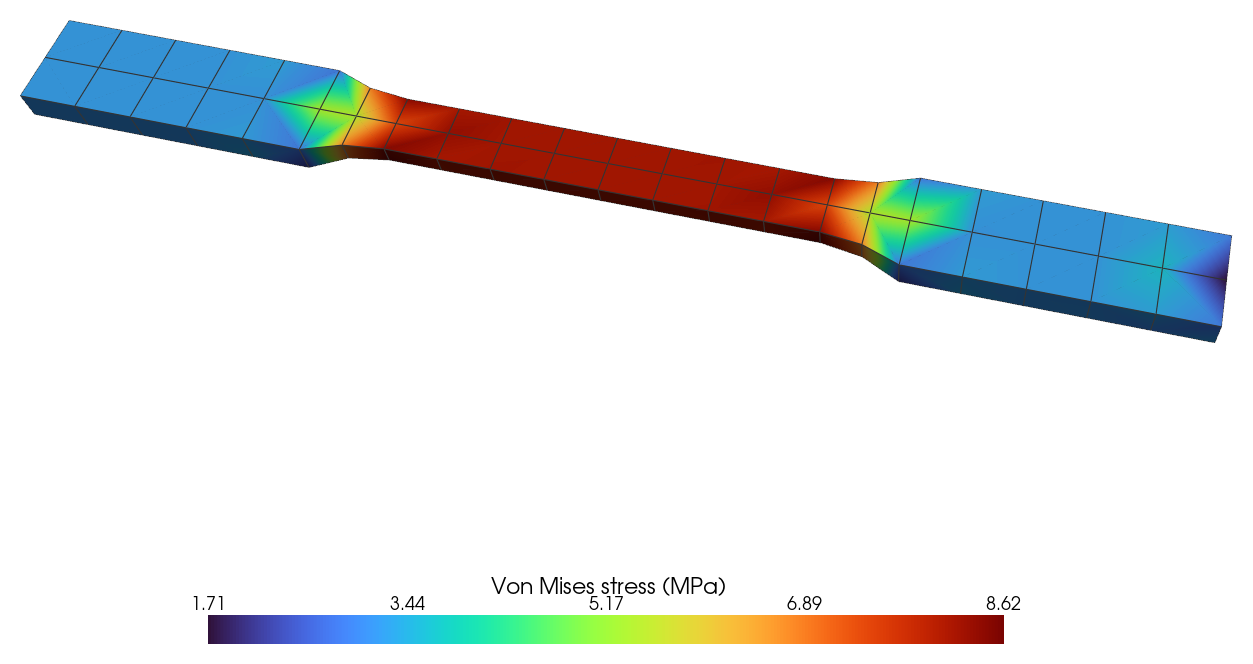
I modeled a tensile dogbone three ways: full, half, and quarter, each cut along a plane of symmetry.

ModelElementsPeak von MisesMax displacement
Full2764.29 MPa0.0027 mm
Half1158.62 MPa0.0054 mm
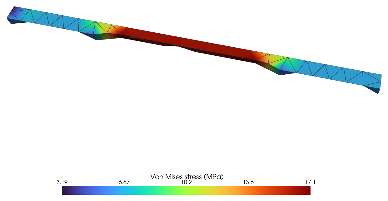
Quarter10617.1 MPa0.0109 mm

Peak stress and displacement double with each cut. That's the pattern you get when the full load stays on a model with half or a quarter of the cross-section, which makes it a good check on how loads have to be scaled alongside symmetry boundary conditions.
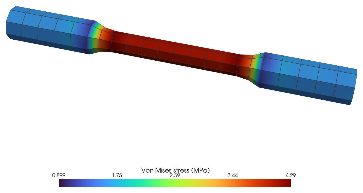
Stress contour plot of the full dogbone
Full model: 4.29 MPa peak.
Stress contour plot of the half dogbone
Half model: 8.62 MPa peak.
Stress contour plot of the quarter dogbone
Quarter model: 17.1 MPa peak.