The problem
The sting is the support that holds a model in the wind tunnel's test section. When the sting moved, it twisted and chattered against the body of the tunnel, which made precise measurements difficult. The guide had to do two things:
- Hold the sensor rods to tight tolerances, so the sting stays steady and measurements are repeatable
- Mount cleanly to the wind tunnel itself
My role
The team was me and the wind tunnel technician. I owned the entire engineering process: working out the requirements with the technician, designing the slot geometry, prototyping, writing the CAM program, and machining the part on the CNC mill.
Design
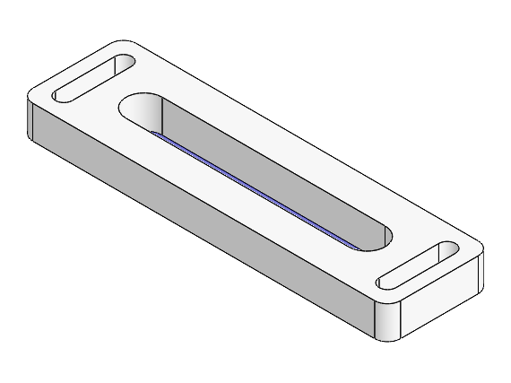
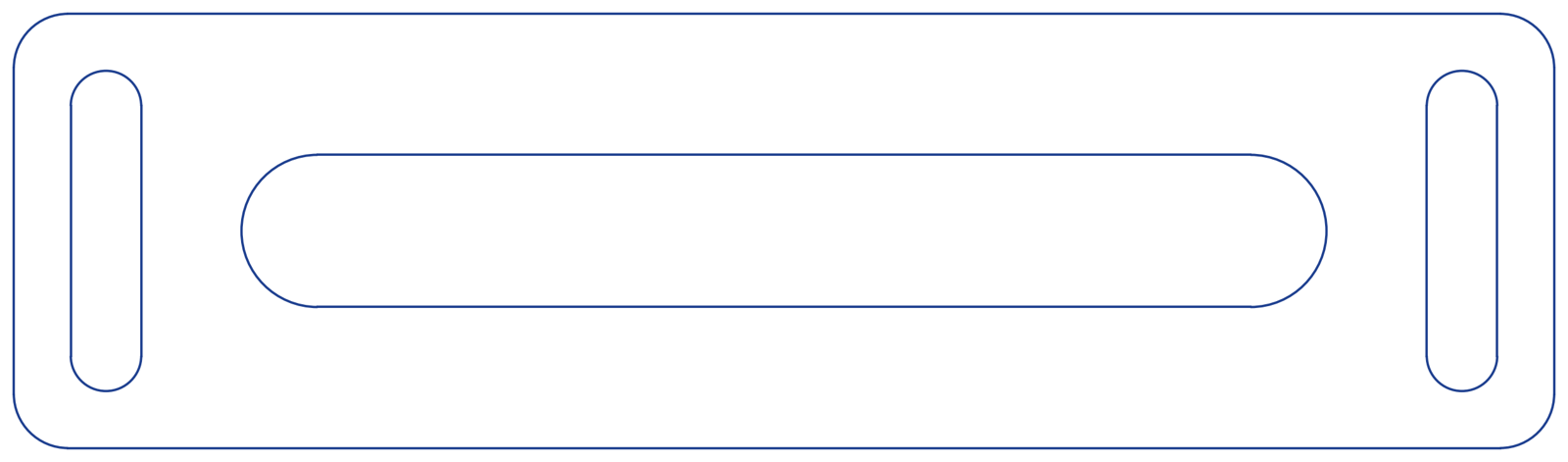
The guide is a flat plate with a long center slot and a shorter slot at each end. The slot layout went through three revisions, mostly to get the tolerances and the fit for mounting right.
Before cutting metal, I 3D printed the design as a low-fidelity prototype. Holding a physical part let me review it with the technician and check for any last-minute additions, and it made it much easier to picture how the final guide would sit on the tunnel.
CAM program
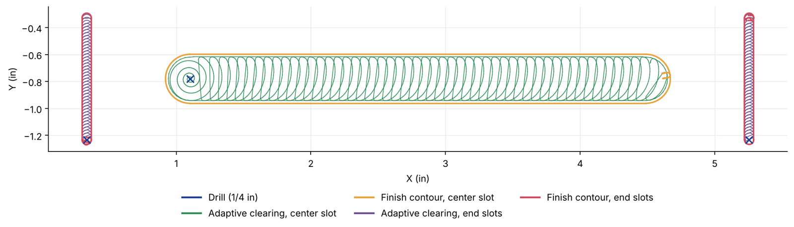
I programmed the part in Fusion 360 as six operations on a 3/16 in flat end mill, a 1/4 in drill, and a spot drill:
- Spot drill and drill the three entry holes, so each pocket starts from a hole instead of plunging the end mill
- Adaptive clearing of the center slot, then a finish contour to size
- Adaptive clearing of the two end slots, then their finish contours
Adaptive clearing keeps the tool engagement constant, which is gentler on a small end mill in aluminum than a conventional pocket. A separate program handles the bore.
Machining
The first part came off the mill with a problem: the vise's clamping force squeezed the plate along its length, and both sides of the long center slot bowed inward, narrowing it. I re-machined the slot and opened the slot width by 1/16 in.
Results
The wider slot gave a slightly looser fit, but the long screw slots at each end let us adjust the guide as we mounted it, so the extra clearance didn't matter. The sting now slides smoothly through its full range of motion without twisting or chattering against the tunnel.
What I learned
The biggest lessons were tolerancing and workholding. Aluminum is soft, so how hard you clamp matters: with a long slot running along the vise rails, the clamping force alone was enough to bow the walls and change the finished width.